The Laserdisc format
A laserdisc stores truly analog video and audio onto an optical storage medium. This is called the Laserdisc format, often abbreviated to LD. It is also sometimes referred to as LaserVision, especially in older publications. There are two main versions of the format - one for NTSC and one for PAL. Additionally, the format was later extended to make a provision for encoding a digital signal, which follows the Redbook (CD) standard, alongside the analog signals.
How is it analog?
The recording surface of a Laserdisc is very similar to a CD. It consists of a disc surface, on which a continuous spiral is formed, made up of “pits” and “lands”, where a laser has “cut” pits into the surface to represent data. A CD works in the same way. How then is a Laserdisc fully analog, while a CD is considered a digital storage medium? The answer is this - on a CD, there’s a regular, fixed period at which the CD surface is “sampled”. If we’ve changed between a pit or a land since the last sample point, it’s a “1”, otherwise (no change) it’s a “0”. Laserdiscs don’t work in this way. With a Laserdisc, the length of the pits/lands has no fixed “frequency” or “duty cycle” like on a CD. Instead, the physical length of the “pits” and “lands” determine the shape of an analog waveform. While it’s a “pit”, the waveform is pulled downwards, whereas while it’s a “land” the waveform is pulled upwards. This is a truly analog waveform, and power from the laser is processed by analog circuitry to reconstruct the waveform. There is no fixed quantization rate of the data, and no specific sample rate of the pits and lands will ever represent a 100% true reproduction of the data. While variations of a few nanometres in pit/land length would have no effect on the resulting data for a CD, on a Laserdisc it will alter the generated signal. This is what makes it analog. Here’s a snippet from the Pioneer Tuning Fork Audio Service Guide No. 6, which goes into significant technical detail on the design of the Laserdisc format and its players:
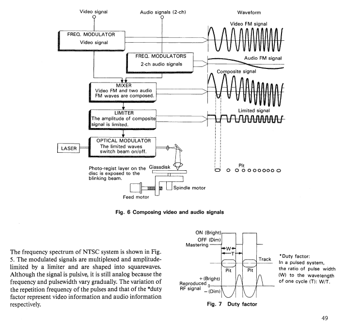
How is data encoded?
All Laserdiscs encode data as a single analog waveform. That waveform is a multiplexed RF (radio frequency) signal. What does that mean? It means separate signals have been frequency modulated together with their own carrier waves at a certain frequencies, to mix several analog signals together into one analog waveform. By getting a “phase lock” on one of the signals, you’re able to “tune into” that signal and demodulate it to turn it back into its own, distinct analog waveform. This may sound like magic, but it’s how an analog antenna signal works, be it FM radio or old-school analog broadcast TV signals. This is why it’s called RF - radio waves were the “original” carrier used for these kind of signals. It’s how you’re able to have potentially thousands of separate TV channels all transmitting their separate content to your TV on a single wire.
It’s important to note, these signals are not truly, fully independent. That’s impossible. With a multiplexed RF signal, there is always “cross-talk”, where at certain moments in time, the content of one signal influences another. The idea however is, the carrier frequencies are not close multiples of each other, and there’s a very, very high data rate involved (IE, in the MHz range for video signals), so those “cross-over” influences occur for incredibly small moments in time. Additionally, due to the use of frequency modulation, the signals are rapidly oscillating waveforms with a varying frequency and a lower amplitude. This makes its influence on other frequencies like a kind of low-level noise that averages out to 0.
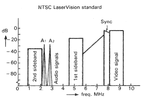
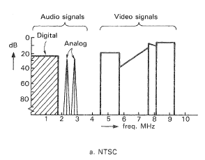
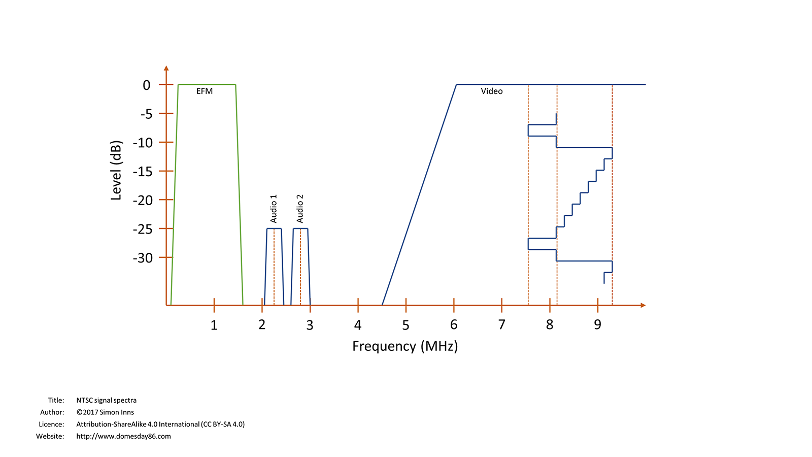
There are two separate and distinct RF encoding formats - PAL and NTSC. Each of them have different capabilities, and encode data slightly differently. Here’s the NTSC encoding format from the Pioneer Tuning Fork Audio Service Guide No. 8, and the Domesday Duplicator wiki:
And here’s the same for the PAL format:
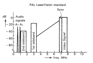
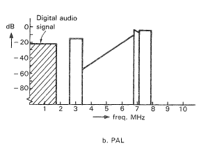
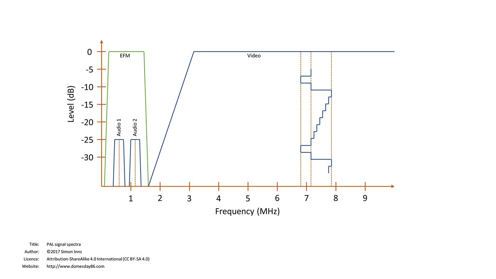
Unfortunately, due to frequency band choices made when the PAL encoding was chosen, it wasn’t possible to retro-fit the digital “audio signal” (Redbook CD) into the signal without removing the analog audio channels. This means while NTSC Laserdiscs can use two analog audio channels in combination with CD data/audio, PAL Laserdiscs have to drop the analog audio channels in order to use a CD signal.
The LaserActive only ever supported NTSC video signals. The Pioneer CLD-A100 is an NTSC-only player. Many games require the use of both analog and digital audio in order to achieve their results, so a PAL version of these games would not have been possible in most cases. Since the focus of this page is on the LaserActive and its titles, the PAL format will not be discussed further, however apart from this significant limitation in audio track support, it is essentially equivalent to NTSC in terms of capture and decoding considerations in all material that follows here.
Can’t we just use a video capture card?
Good question. I first looked at the problem of archiving LaserActive titles back in 2009. My first thought was this - extract the decoded “Redbook” digital CD data, rip the analog audio/video to a recording using a capture card. I was able to extract the CD data after some significant effort. As for the analog signals, there were multiple cards I had access to which were able to make a recording of the visible video signal, and the analog audio was relatively simple, however it quickly became apparent there were several problems with this approach:
- Capture cards generally showed degraded video quality from the source video
- Lossless video capture was not possible in practice
- Video was assumed to be interlaced and compressed as such on all but one device
- Control signals in the vertical blank region could not be captured on any device
- Lead-in and lead-out regions could not be captured
All of these meant that while I could make a pretty recording, that data would be effectively useless for archival and future emulation. Let’s go through the “why” in a little detail.
First of all on quality - for a true archival of a medium, we need to capture in as close to full fidelity as possible. Image degradation was clear in the backups I made. This could have been mitigated however, by getting the best quality analog capture device, and taking multiple analog captures, them using them to error correct each other. That is, if lossless video capture was possible. In reality, all capture devices of the era were lossy. This is because the data rate required to do true lossless capture exceeded the transfer rates of the PCI bus most devices used, or if not that then the Hard Drive being used to store the data. All capture devices I was able to find, after some extensive research, had this limitation. The signal quality was degraded. This was quite disappointing, but I may have proceeded with that approach anyway, if not for some more serious limitations.
The biggest issue was control signals. Analog video, either PAL or NTSC, is made up of more than the visible image area. There’s “blanking” regions, both vertical and horizontal, which hold information generally “cropped” out of the visible display. All capture cards dropped that information entirely. These regions contained control signals, which were used to give instructions to the Laserdisc player. These signals for example contain “picture stop codes”, instructing the player when to automatically pause playback at various points, and critically they contain timecode information telling the player what part of the video it’s currently looking at, in addition to various other signals. Most capture hardware had no way of capturing this region of the image. The ones that did exposed features which were specific to VHS or broadcast video signals, but were useless for Laserdisc control signals, as they didn’t understand how to decode it and/or they were looking at the wrong lines of video.
Another critical issue was the assumption of interlacing. The LaserActive specifically, is not just a normal Laserdisc player when it’s playing back games. At that point, it’s a slave device under the control of computer software, and many features of the player were provided to allow that software to do unusual things not typically done on a traditional Laserdisc, or a traditional composite video stream. That includes Laserdisc-based arcade hardware, which had more simplistic control of the player and less features to use. Here’s an example full NTSC frame from the Myst B prototype on the LaserActive:
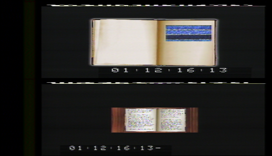
NTSC video is made up of 525 lines of video at around 30fps, split into two fields appearing sequentially in the frame, with 262.5 lines for each field. That’s what you’re looking at above. How is that “.5” or “half a line” done? Well between the two fields, vertical retrace occurs, so on your CRT display the electron beam restarts at the top of the screen, but we actually move “half a line” further down. These are traditionally called the “odd” and “even” fields, because they literally get drawn interleaved on the monitor, one field drawn between the lines of the other field. In traditional NTSC video, these two fields are showing the same image, one being the odd lines and one being the even lines, so you end up with an (approximately) 30fps image from your two fields in your frame. The problem here is, as shown above, many (possibly all?) titles on the LaserActive don’t work in this way, at least not for the entire video stream. The player has a digital memory buffer, and allows the software to decide at any moment whether to display the full interlaced frame, or whether to selectively use just the even or odd field, and line-double it to make it be the only image shown. This cuts the effective vertical resolution in half, but allows two separate video streams to be used at the same location. If you just play back the video as shown without separating the fields, you end up with a mess of two overlaid images. Here’s a picture taken of a LaserActive title showing this occurring, with a shutter speed picked to help you see the two images somewhat separated:

The problem again with analog capture cards, is they don’t expect this situation. They expect typical interlaced NTSC video, nothing else. Due to that, when they perform the capture they’ll assume it’s an interlaced signal grouped into 30fps frames, and when they perform lossy compression on the data, they’ll interlace them together and compress the result, causing these two distinct video streams to “bleed into” each other. This is unrecoverable. The images have been destroyed.
The last problem is to do with the lead-in and lead-out regions. For normal Laserdiscs, this may not seem all that important. There’s TOC (Table of Contents) information for the Laserdisc video itself in the lead-in area, but there’s also chapter markers and timecode data in the VBI region of each field, so that information can typically be reconstructed. It’s also the case that disks sometimes put video in the lead-in and lead-out regions of the disc, but these couldn’t be “seeked to” on a typical player, so if you’re just archiving a better quality version of a movie on a Laserdisc for example, you might not care. For the LaserActive though, these titles are often rare and quite hard to get. Preserving the entire disc, including the lead-in and lead-out, is greatly preferred, even if those regions in many cases just contained blank video/audio streams.
It’s not just about the visible video and audio on the LaserActive though. The LaserActive uses a Redbook encoded CD data track, and not just for audio, for data too. The binary data for the game, including the code and any other digital resources it needs, are encoded into this CD data. Part of the Redbook CD standard is the lead-in region for the CD, which contains the TOC data for the disc. This is a separate and distinct TOC from the one included on the video stream. It can’t be easily reconstructed if it’s missing, and it’s vital, as the LaserActive does make both the analog video and digital CD TOC data available to the software running on it. The TOC data tells the player where chapter markers are for the CD content, and the software can choose to seek by either analog or digital time/frame/sector/chapter information. If this data isn’t properly preserved in a capture, it could be impossible to emulate the game properly. Getting the player to seek to and play these regions of the disc to capture them requires extra effort, and not every player is able to do this.
How do we archive the data?
How then do we archive the data from a Laserdisc? The answer is this - We need to get a capture of the “raw” RF signal straight from the laser pickup on the player. This is that waveform which is built directly from the pits and lands, as detailed above. Since this is an analog signal, we need to sample it at a high enough rate to ensure we can reconstruct the analog signal from our quantized digital representation with enough accuracy to give a good result. In the case of a Laserdisc, that magic sample rate is 40MS/s, or in other words, we need 40 million samples of that waveform every second at regular intervals, with a reasonably high number of bits, to get a clean signal. There are ADCs (Analog to Digital converters) that are capable of capturing data at that rate, which we then need to stream back to a PC and save to disk without losing any data along the way. A device was designed around such an ADC to do this very task, called the Domesday Duplicator, which is capable of sampling at 40MS/s at 10-bit precision. This is the device we use for archival. It was the first such device made available to the general public, and it was built and calibrated specifically for Laserdisc archival. Although competing lower-cost alternative devices have been used in other scenarios since, the Domesday Duplicator is the only device I recommend using for archival purposes of LaserActive titles.
The Domesday Duplicator will give you a 10-bit raw RF capture from the player at 40MS/s. What does a signal like this “look like” in practice? It’s just a big analog waveform. Literally a mono wav file could store it. Here’s an example of an RF signal in that exact format:
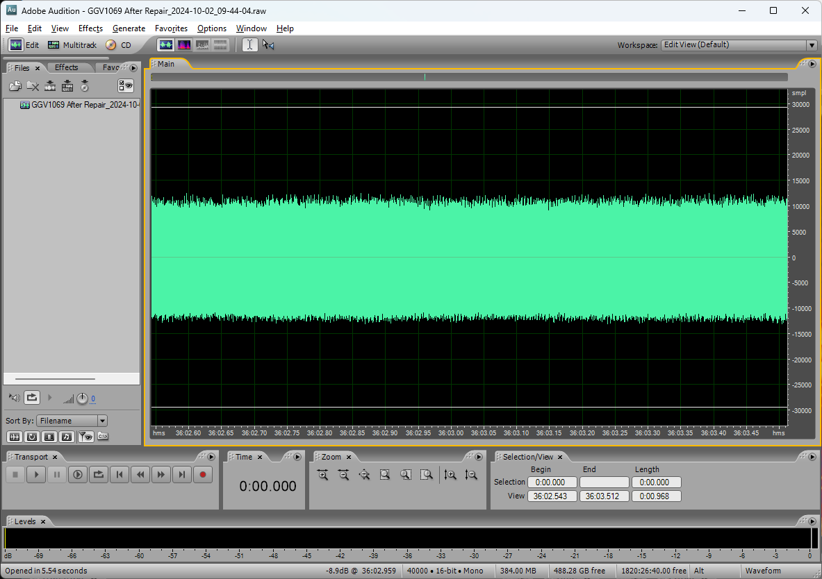
Since this is just a wav file, you can use audio compression codecs to compress it. The FLAC compression algorithm, being lossless and giving a good compression ratio, is the best choice. This is the format you should save in, and the decoding tools we will be using work with this format directly.
The raw RF capture is the only, true complete capture of the Laserdisc content. Any captures you make must preserve this original file. You may extract derived data from this, such as decoded video, audio, and digital content, however never delete the source RF file. Video decoding is not perfect, and analog media is not perfect. Your particular source copy may have defects, such as from scratches or minor errors during manufacture, which affect the quality. With the source RF data, multiple rips can be used to cancel out errors in each other. As the decoding software advances, better picture quality may be obtained by re-running the decoding process, or by using different decoding settings or parameters. The RF file is your backup, and must be preserved.
Be aware - raw RF captures are large. Very large. To store a single rip of a single side of a CAV Laserdisc (used by all LaserActive titles), it requires around 150GB of storage in raw uncompressed samples, to get the 34 minutes or so of recording time to capture everything from the beginning of lead-in to the end of lead-out. When you compress with FLAC, you can expect that to drop to around 50GB. That’s per rip. I recommend 5 rips are made per side, per unique copy, for error correction purposes, and for single-sided discs a single rip of the “B side”, which usually contains a standard “content is on the other side of this disc” message, for completeness. This means you can expect around 300GB of storage will be required per LaserActive title. Ideally each title will get ripped at least 3 times from unique copies. That means for archival, we’re talking around 1TB ideally to properly preserve a single title.
How do we decode the data?
A full treatment of signal demodulation and decoding will not be given here. Your best reference for this in action is the Domesday Duplicator Wiki. Although the Domesday Duplicator is primarily a hardware capture device, and doesn’t involve decoding itself, it gives a good description of the entire problem we’re trying to solve here. It will in tern reference ld-decode, which is the software package that was written to do the actual decoding of these signals in software on a PC.
RF demodulation is not new, and there are a lot of reference materials for how this is done in the analog domain. Demodulation of high-bandwidth RF in the digital domain however is a much more recent problem. Here’s what our modulated RF signal looked like again:

Here’s what a demodulated NTSC video signal looks like, IE, this is what you’d see if you were looking at the composite video output of any video equipment:
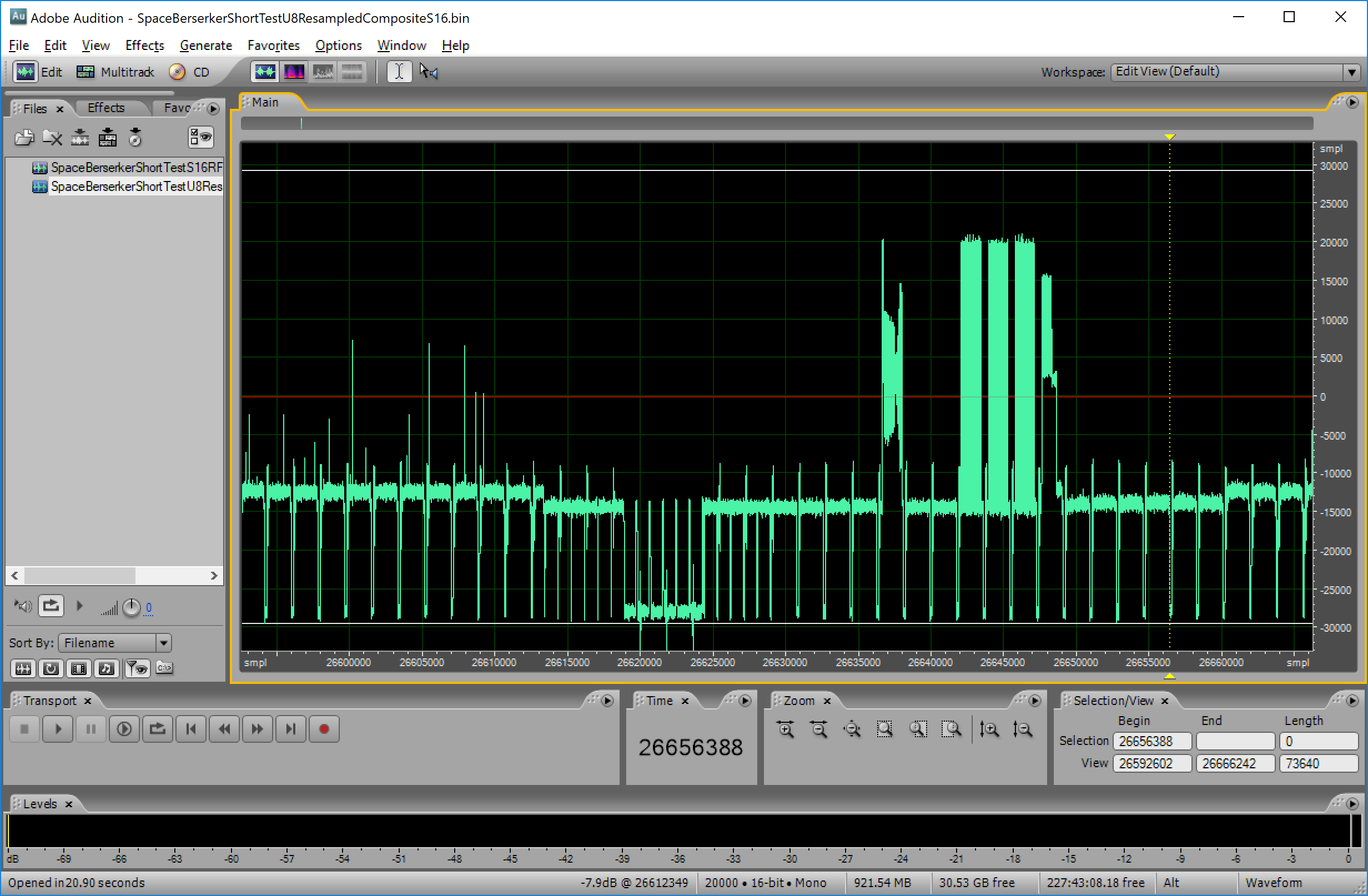
In this case we’re looking at the end of a field, the vblank period, and the start of a new field of NTSC video. I won’t go further into composite video structure here, there are many texts and references on that elsewhere. The question is, how do we extract this signal from an RF waveform like shown above? Well let’s see what happens when we look at the RF signal in spectral view:
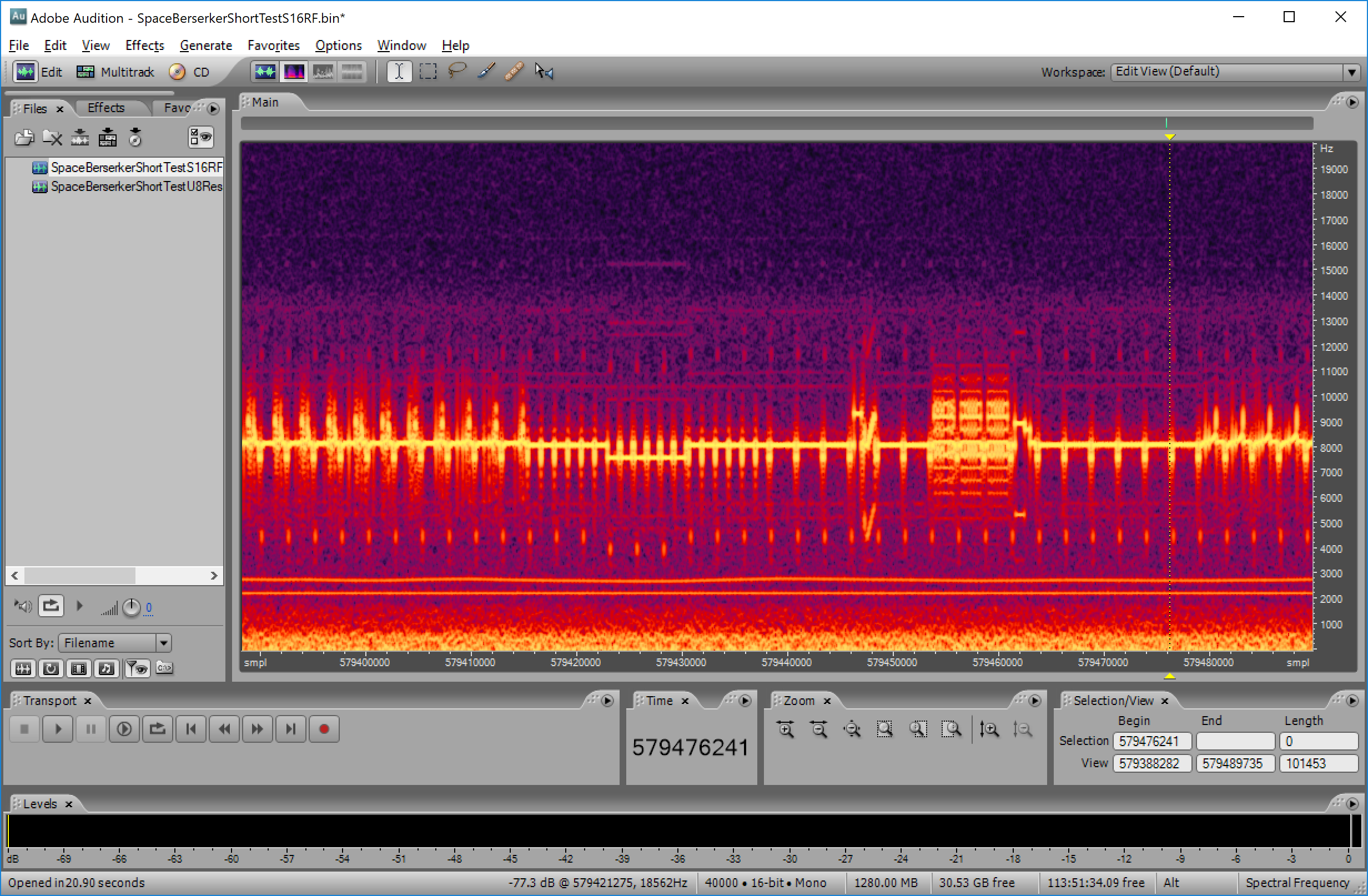
That’s interesting isn’t it? You can see the same video signal coming out in spectral (frequency) view, and what’s more the frequency reading on the right, if you multiply it by 1000 (since our wav file was really 40MHz, not 40KHz like we told the software here), you’ll see it lines up with the frequency bands shown earlier for the NTSC Laserdisc format:

Here we can clearly see the composite video signal, the two analog audio channels encoded below, and at the bottom, a band of low-frequency noise which contains the digital channel data. we can also see the harmonic sidebands coming through, giving lower intensity “echoes” of the data at lower and higher frequencies than the encoded frequency.
This is what a modulated signal is. We’ve taken a source analog waveform, and used the amplitude of that source signal to adjust the frequency of a carrier wave, so basically our data is no longer represented as sample values expressing amplitude, instead it’s expressed as variations in frequency of another signal from an expected “baseline” frequency. If we can “phase lock” onto the carrier frequency, we can calculate the frequency deviation from the carrier frequency from moment to moment, and therefore reconstruct the original signal, within a margin of error and subject to noise/interference. Separating multiple overlapping signals from one combined RF signal is called demodulation, and it’s the first step in the decoding process.
The next step is to turn the demodulated signals into something useful. You might think you can just plug the analog audio for example into a player and listen to it. Not quite. You see, we need to perform TBC (Time Base Correction). The player didn’t necessarily give us a sampling at a perfect even rate. The signal can be stretched or compressed, often in a kind of “wavy” pattern. This means even a simple signal like our analog audio will sound distorted if we just use it directly after demodulation. What we need to do instead is use some kind of regular “marker” to determine where we should have been vs where we were during playback, and stretch or compress the signal to fit within those markers. This is done using markers in the video signal, IE, the regular horizontal and vertical blanking markers. The player uses these markers to time base correct everything, not just video, but audio too. We need to do the same.
After time base correction, we have our (hopefully) time accurate separate data streams. We then need to decode them. You might have thought that was a solved problem years ago. Not so. In fact, until the Domesday86 Project I could find no evidence decoding raw NTSC or PAL video signals in software from raw samples had ever been done before. I looked extensively back in 2010 trying to find such an option, commercial or otherwise, and it didn’t exist. Perhaps that isn’t surprising, seeing as analog video was effectively irrelevant at that point. It is also a non-trivial problem, and perhaps more significantly, the data transmission, storage, and processing requirements meant it was effectively impossible until recent years. Why? The size of the data is massive. It may seem strange, but your humble Laserdisc player, first released in the 1970s, going to your analog TV, was decoding and displaying in real-time a signal we still, to this day, with the most powerful computers, cannot process in real-time digitally. Ultimately ld-decode came through here, and because decoding NTSC/PAL signals is not unique to Laserdisc hardware (in fact it’s one of the most niche applications), we have the logical expansion to other devices in the vhs-decode fork.